
Electrolysis is a chemical process that involves the use of an electric current to drive a non-spontaneous chemical reaction. It is commonly used to separate compounds into their constituent elements or to induce chemical changes in a substance. Examples in school include understanding the stoichemistry of water, and the plating of one metal to another. Understanding electrolysis requires knowledge of its basic principles, the components involved, and the underlying reactions.
In electrolysis, a substance is either dissolved in a liquid or in a molten state, known as an electrolyte, which allows the flow of electric charge. The electrolyte contains ions that can either be positively charged (cations) or negatively charged (anions). Two electrodes: a cathode (negative electrode) and an anode (positive electrode), are submerged in the electrolyte. These electrodes are usually made of inert (unreactive) materials like carbon or platinum, (copper is used in electroplating experiments).
- Electrolysis means splitting with electricity
- Completing an electrical circuit using free ions in a liquid or solution
- Needs power source (DC)
- Needs electrodes; somewhere for the ions to go (be attracted to)
- Used to ‘plate’ metal in industry, to extract metal from its ore, manufacturing chemicals, and is also employed in pH probes
Understanding Electrolysis: The Set Up:
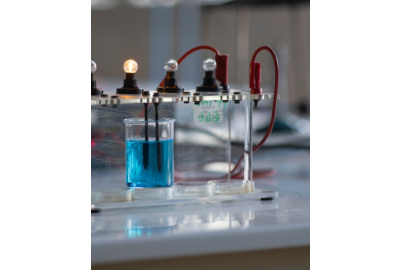
- The electrolyte solution is added to a suitable container.
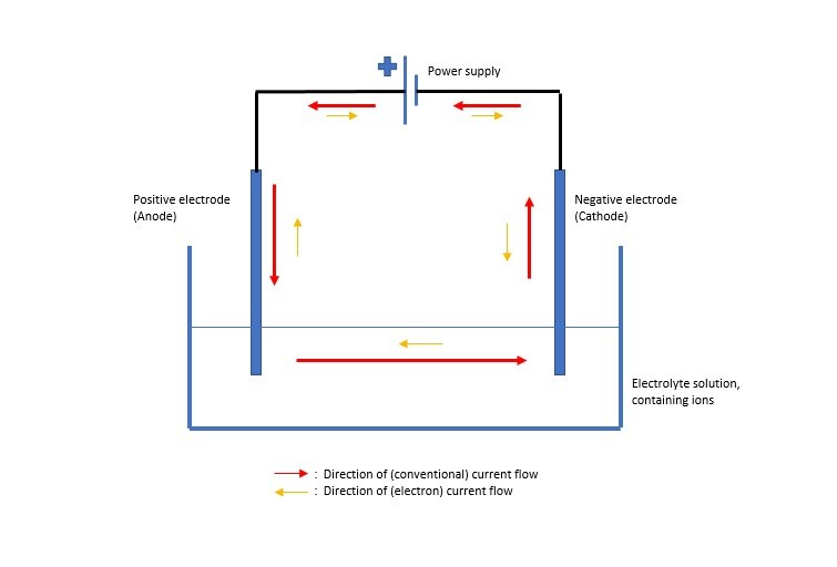
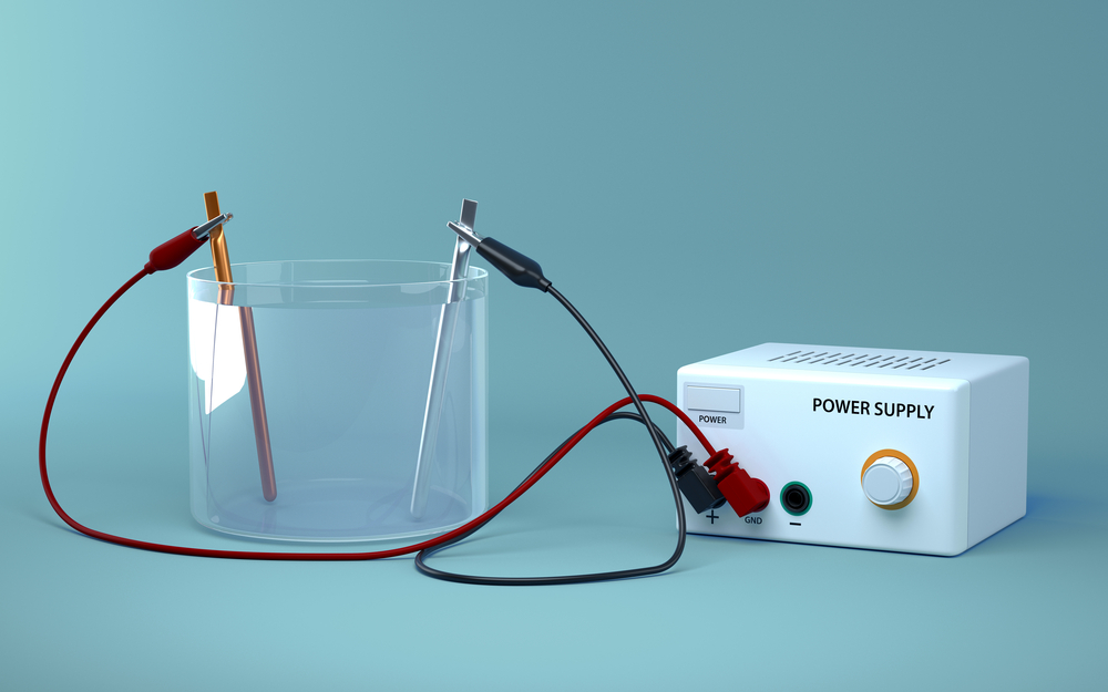
- Electrodes and a power supply are added as in the diagram above.
- The power supply is switched on and bubbles should appear at one of the electrodes.
- Depending on the electrolyte and the electrodes used you may see; plating of a metal at one electrode, a diminishing electrode (as it is used in the reaction), gas produced at one electrode.
- Adding a microammeter into the circuit, (in series) will indicate that current is flowing.
The Science:
Electrolysis is a good way of proving the existence of ions in a molten state or a soluble state.
Ionic compounds (typically a metal and non-metal) are able to be split into their constituent ions (charged particles) with the addition of power.
These charged particles act to bridge the ‘gap’ in the circuit above. The negative ions will be attracted to the positive anode and at the same time, positive metal ions will be attracted to the cathode (negative electrode).
Molten Compound:
In a molten ionic compound this is a straightforward split, e.g., molten lead bromide (PbBr2):
PbBr2→ Pb2+ + 2Br-
The bromine ions (Br-) will be attracted to the anode (+) and gain electrons here to become bromine gas (Br2), this will be given off at the anode.
The lead ions (Pb2+) will move to the cathode (-) and lose electrons to it becoming lead solid (Pb) and molten lead drops would be formed here.
Note:
*The reason that this ‘connects’ the circuit becomes clearer when you see that conventional current flow is described as moving from the positive terminal of the power source towards the negative terminal. The flow of electrons in a circuit, however, has been shown to be from the negative terminal to the positive, therefore the Pb2+ flows to the negative electrode and gains electrons coming the other way, to become solid lead. The Br- flows to the anode, losing electrons to the anode (which then continue the electron flow around the circuit) and becoming Br2 gas
Aqueous Solution:
Here, there are also the ions in the water to be aware of: H+ and OH-
Some of the most common solutions used in electrolysis (in school) are sodium chloride and copper sulfate, and sulfuric acid (used in the electrolysis of water, in the Hofmann voltameter)
Sodium chloride solution, NaCl (aq):
NaCl → Na+ + Cl- also, because this is a solution:
H2O → H+ + OH-
Chlorine ions and hydroxide (OH-) ions will head to the +ve anode
Sodium ions and hydrogen ions will head towards the – ve cathode
But how do you know what is given off/comes out of solution at each electrode?
At the Cathode:
For this you need to know how reactive the ions are with respect to each other.

The more reactive an element is, the easier it forms ions, but it is also harder for it to return to the atomic state (i.e., to pick up electrons and return to neutral), in other words it prefers to stay as ions in solution.
So, if hydrogen is the less reactive ion at the cathode, hydrogen gas will be produced, because the other (metal) ion is more reactive and wants to stay in solution.
If hydrogen is the more reactive element at the cathode it will stay in solution, and the other ion will form solid metal instead.
For the aqueous NaCl example above:
Hydrogen is less reactive than sodium, so: 2H+ + 2e- → H2(g) at the cathode
Sodium stays as Na+ in solution
For aqueous silver chloride, the hydrogen ions stay in solution (as hydrogen is now the more reactive element), and silver metal is deposited at the cathode: Ag2+ +2e- → Ag(s)
At the Anode:
Here, the negative ions are collecting, these will be OH- (from the water) and another ion.
If this other ion is a halide (chloride, bromide, iodide) then the halogen gas will be produced (chlorine, bromine or iodine).
If it is anything else (sulfate, nitrate etc) then hydroxide ions will form water and oxygen which will be produced at the anode.
So, for aqueous NaCl:
2Cl- (aq) → Cl2(g) +2e- and the OH- stays in solution (this will make NaOH with the Na+ ions already in solution). You can test for chlorine gas by seeing if it bleaches some damp litmus paper.
So, the full equation for this would be:
2NaCl(aq) + 2H2O(l) → 2NaOH(aq) + H2(g) + Cl2(g)
Electrodes:
These are usually carbon or platinum. Inert (unreactive) electrodes are often used in electrolysis set ups so that they act as a conducting element in the circuit but are not affected by and don’t take part in the reaction of the ions in solution.
If you use non-inert electrodes, they can decompose in the electrolyte solution and add to the reaction. This can be useful if you want to purify a metal (such as copper).
- Using impure copper as the anode and a tiny piece of pure copper as the cathode, and copper sulfate solution as the electrolyte, copper ions will transfer from the anode to the cathode, decreasing the mass of the anode and increasing the amount of pure copper at the cathode.
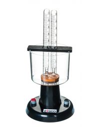
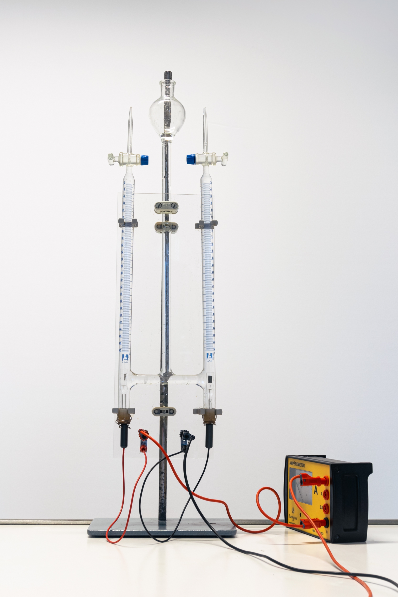
Electrolysis of Water: the Hofmann Voltameter
Although the Hofmann apparatus is used with dilute sulfuric acid, it is actually to demonstrate the electrolysis of water, and the stoichemistry of water (2 molecules of hydrogen to one of oxygen).
The aqueous solution contains sulfuric acid, H2SO4 and water, H2O
At the cathode there will be H+ ions gathering. As there are no other positive ions here,
H+ will gain electrons and become hydrogen gas: 2H+ +2e- → H2(g)
At the anode there will be OH- and SO42- gathering. Because there is no halide present, the sulfate ions will stay in solution and the OH- will discharge at the electrode and water and oxygen gas will be produced: 4OH- → 2H2O(aq) + O2(g) + 4e- and the ratio of hydrogen
gas: oxygen gas produced is 2:1.
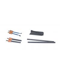
Making Mini and Microscale Electrolysis Apparatus
Often it is useful for students to use their own, mini, electrolysis apparatus.
AQA specification, required practical 3: Electrolysis of copper chloride
OCR specification PAG C2: Electrolysis of copper sulfate and electrolysis of sodium chloride
Edexcel Core practical 3: Electrolysis of copper sulfate
WJEC specified practical: Investigation into electrolysis of aqueous solutions & electroplating
The Benefits of Using a Microscale System Include:
- Minimal use of solutions, and thus minimal production of noxious gases
- Minimum waste at the end of the practical
- Every student gets the chance to set their own electrolysis set up
The Disadvantages Include:
- Fiddly equipment to set up
- The electrolysis cell is not in the usual orientation, which some students may struggle to understand
- It is not good as a class demonstration set up
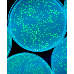
Example of Microscale Set up in a Petri Dish:
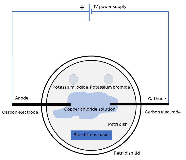
- In this set up the copper chloride solution should be at 0.5moldm⁻³ concentration, and enough drops should be added to the petri dish to reach the electrodes. Do not flood the dish with solution.
- The copper chloride will sit in the dish without spreading out, allowing a piece of blue litmus to be placed at the bottom edge of the dish.
- 2 drops each of potassium bromide and potassium iodide (both at 0.5moldm⁻³) can be added at the top of the dish to show displacement reactions, if desired.
The petri dish lid should be added before switching on the power.
Note: a small amount of chlorine gas will be formed. (although there will be less if the potassium bromide and iodide solutions are added).
- Once the power is switched on, copper will form at the anode, and chlorine gas at the cathode.
- The chlorine gas will bleach the blue litmus paper to colourless.
- If the potassium bromide and potassium iodide are included, the chlorine will displace the iodine and bromine in those compounds (becoming potassium chloride in both cases) and iodine and bromine will be formed, showing as a purple (iodine) or brown (bromine) colour in the drop of solution.
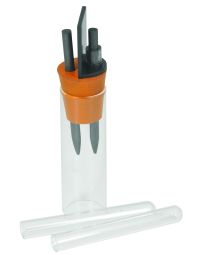
The carbon electrodes need to be fixed through the sides of the petri dish. This can be tricky, but a hot nail or a small drill (moving fairly slowly) can help create the hole. Add some glue or sealant around the electrode/petri dish join to hold the electrodes in place. The lid will just sit on the top.
See video below to a Cleapss video showing microscale electrolysis of copper chloride:
A slightly larger (miniscale) system can be used, using 100 mL beakers and a small petri dish lid placed over the top:

Again, holes need to be added to the lid to fit the electrodes, and sealant/glue used to fix them in position. The remaining wires etc can be attached easily with crocodile clips and solution added to the beaker.
(Edexcel uses a slightly different version, with the set up appearing upside down, allowing small test tubes to be placed over the electrodes to collect gases. See the specification for more detail).